|
N-1M: the
first Northrop flying wing
by E.T. Wooldridge
Jack Northrop became interested in the development of the cleanest
possible airplane early in his career as an aircraft designer. In 1923, as
an engineer for Donald Douglas in Santa Monica, California, Northrop
continually explored advanced designs for aircraft, seeking new ways to
eliminate drag and the severe penalties in aircraft performance it
imposed. Even then, he envisioned an airplane without protruding surfaces
that did not contribute in some way to lift. He even undertook the design
of a tailless, all-wing glider as a "pastime" project, but never finished
the aircraft, due to other commitments and lack of funds. In 1927,
Northrop designed the incomparable Lockheed Vega as the best possible
compromise that could be made with known and proven elements. Even this
aircraft, with its conventional arrangement of wing fuselage and tail,
gave hints of the unconventional concepts that were beginning to form in
Jack Northrop's mind.
Northrop left Lockheed in 1928, and formed a small
company, the Avion Corporation, in the Burbank/Glendale area, to further
explore the idea of a tailless craft. His 1929 Flying Wing evolved, an
aircraft unusual in appearance and performance, but more noted for its
unique all-metal, stressed skin, multi-cellular construction. Although
financial considerations forced suspension of further development of the
airplane, its unique structure paved the way for major Northrop
contributions to aviation in the perfection of all-metal construction.
Noted f or its multi-cellular construction, Northrop's 1929 Flying wing,
with its twin booms and tail structure, was a cautious step toward his
first true flying wing design in 1939.
In 1932, Northrop formed a new Northrop Corporation at
El Segundo, California, in partnership with Douglas Aircraft. As Northrop
continued to design and produce airplanes of a conventional nature, he
found another opportunity to test his ideas with a wind tunnel model in
1937. He was assisted in his project, designated Model 25, by Edward H.
Heinemann, who in his own right would have a profound impact on the design
of military aircraft in the United States. Without any significant
financial support, the project was abandoned after wind tunnel tests
showed that it needed a tail.
In 1938, the Northrop Corporation became the El Segundo
division of Douglas, with emphasis on production design. More interested
in experimental design, Jack Northrop resigned, and in 1939 formed his own
company once again, Northrop Aircraft Inc. Business came in the form of
contracts for construction of Consolidated PBY subassemblies, a Norwegian
order for 24 Northrop-designed N-3PB patrol bombers in March 1940,
followed by a contract for co production of Vultee-designed Vengeance dive
bombers. Northrop finally had the financial wherewithal, facilities, and
ultimately, government interest, to enable him to pursue his interest in
research and development and more specifically in the flying wing. As
Northrop progressed through the early design stages of his first true
flying wing, he sought the advice and technical expertise of one of the
world's leading aerodynamicists, Dr. Theodore von Karman, Director of the
Daniel Guggenheim School of Aeronautics at the California Institute of
Technology (GALCIT), and von Karman's assistant, Dr. William R. Sears.
Also available were all of the technical data and information in foreign
aeronautical literature and NACA reports. Northrop and his assistant chief
of design, Walter J. Corny, conducted extensive wind tunnel tests with a
number of flying wing models. The result was an aircraft incorporating the
latest thinking on buried engine design, new airfoil sections of low drag
and improved stability, and the use of various high-lift devices,
spoilers, and flaps.
Northrop viewed the diminutive N-1M (Northrop Model 1
Mock-up), with its 38-foot wing span, as a flying scale mock-up, perhaps
one-third or one-half full-scale size. To achieve the efficiency and
economy possible with a pure all-wing design, Northrop envisioned a
commercial cargo airplane of a minimum 70-foot span, providing a maximum
thickness of about 6 feet. With wing thickness growing in proportion to
increase in span, a thickness of 15 to
20 feet would ultimately be possible. Depending on
whether the use of the aircraft would be military or commercial, gun
turrets, passenger cabins, and other special loads could be accommodated
by bumps or projections that would not alter the basic characteristics of
the aircraft.
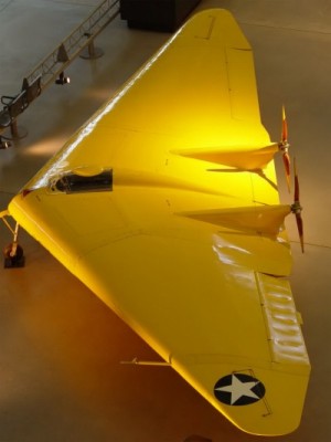
The National Air and Space Museum is fortunate to have
in its collection one of the original models built by Jack Northrop to
investigate his theories of flying wing design. Constructed of balsa wood,
tissue paper, and cardboard, the delicate structure bears a strong
resemblance to the N-1M and incorporates many of the control surfaces
evident in the real aircraft. Hinged wing tips, cardboard flaps that serve
as rudders, and the elevons provide control and balance. The model was
tested in hand-launched free glides to test its stability and flight
characteristics.
The N-1M that evolved from many design studies and
model tests was the first such tailless configuration to appear in the
United States. The experimental aircraft was distinguished by the absence
of any of the unusual appendages; the pronounced anhedral, or downward
droop, of the wing tips gave the airplane a distinctly bird-like
appearance. Aircraft configuration could be varied on the ground between
tests to permit in-flight evaluation of the many variables associated with
wing sweep, dihedral, and the all-wing design. In effect, the N-1M was the
forerunner of today's "variable geometry" airplanes.
Control of the N-1M was accomplished using many of the
same techniques and methods employed by the Hortens in Germany and other
European designers. Elevons operated together for pitch control and
differentially for roll control. Rudder control was accomplished initially
with a plain split flap or "clamshell" at each wing tip. Actuated
independently by the rudder pedals, they opened to produce drag, which, in
turn, induced yaw. Both split flaps could also be opened simultaneously to
increase gliding angle or reduce airspeed, thus serving in the role of air
brakes.
The ICI-1M was of wooden construction, and thus easily
adaptable to the many changes in configuration to which it was subjected
during the flight test program. The aircraft was initially powered by two
submerged 65-hp Lycoming 0-145 four-cylinder, horizontally-opposed engines
driving two bladed pusher propellers by means of extension shafts. The
engines, which were later replaced by 117-hp six-cylinder, air-cooled
Franklin engines driving three-bladed propellers, were cooled by means of
slot-type intakes in the leading edge of the wing.
Engineering and construction of the N-1 M took exactly
one year, beginning in July 1939. The first flight of the N-1M, nicknamed
the "Jeep," was in July 1940, and indeed was an accidental one, as pilot
Vance Breese bounced the airplane into the air during a high-speed taxi
run on Baker Dry Lake, California.
It took only several days of abbreviated test flights
to prompt Jack Northrop to report encouraging results to Gen. H.H. "Hap"
Arnold, Chief of the Air Corps. Northrop reported the airplane was both
statically and dynamically stable about all three axes, with normal stick
forces and good controllability, laterally and longitudinally. The
aircraft was considerably shy of adequate rudder control using the
trailing edge split flap rudders, but Northrop was optimistic about a
solution.
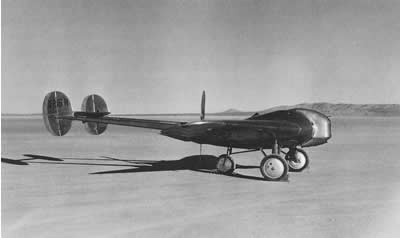
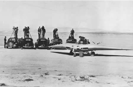
All of the N-1 M's original distinctive design features are evident in
these views of the aircraft at Muroc Lake in June 1941. Droop of 'the wing
tips, with split flap rudders installed, could be adjusted on the ground;
sweepback, dihedral, centre of gravity location (by changing angle of
sweepback), and control surface arrangement were also adjustable. The
faired tailwheel, which prevented excessive rollback on the ground, also
provided some measure of directional stability. The metal bump on the top
of the canopy was added to accommodate the pilot's head.
The N-1 M's test program provided valuable data for its
successor, the N-9M, but it was not without problems. Choosing suitable
power plants became the first, and most enduring dilemma, one that would
plague many of Jack Northrop's piston-engined tailless designs.
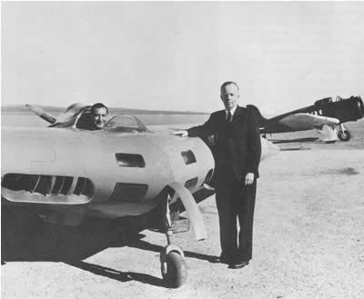
Jack Northrop poses by the N-1 M, while Moye Stephens beams from the
cockpit.
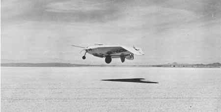
The flat surface of Muroc Dry Lake was the ideal site for early test
flights of the "Jeep," shown here cruising at an altitude of 10
feet.
At an early stage in the test program, it was
determined that the Lycoming engines were totally inadequate for the N-1
M. Moye Stephens, Northrop's company secretary and test pilot who took
over the flight test program from Vance Breese, recalls that the Lycoming
engines could not get the 4000-pound airplane any higher than ground
effect during flights at the dry lake:
"In the initial flights with the Lycoming engines the
ship would climb to about five feet and the increased induced drag
associated with attempts to force it higher would bring it down to a
landing. Continuous flight called for maintenance of a precise angle of
attack. Any increase in the angle of attack and the ship would land. Any
decrease in the angle of attack and the ship would land. The situation
was complicated by a "dead area" in elevator effectiveness. In order to
nose down it was necessary to move the wheel forward a disturbing amount
with no response, and then the elevons would suddenly take over. In order
to keep from banging into the ground it was then necessary to traverse
the dead elevator area in the opposite direction to find the start of
effectiveness. This was moderately unsettling while flying along five
feet off the ground. I temporarily overcame the difficulty by use of the
longitudinal trim flap: a control surface spanning the trailing edge of
the centre section. With this adjusted to create a nose heavy condition,
flight was maintained with a constant back pressure on the wheel. To nose
down it was simply necessary to ease off the back pressure."
Dr. Theodore von Karman quickly came up with a solution
for the problem. Realizing that the extremely thick wing was creating an
airflow separation that was not coming together until aft of the wing, he
suggested extending the trailing edge of the elevons into the closure of
the airflow. The solution apparently had the desired effect.
Early test flights were made in a straight line over
the length of the dry lake, generally at the maximum ceiling of the
aircraft, about ten feet. On one of these flights, Stephens lost one foot
of a propeller tip on the desert floor. Despite the extreme vibration
which broke a rear spar, Stephens landed the ICI-1 M without further
damage.
Replacing the Lycomings with 117-hp Franklins almost
doubled the horsepower. The engines still had to be operated considerably
in excess of the manufacturer's limitations to achieve anything
approaching satisfactory flight. Overheating became chronic, and much time
was lost in attempting to reduce oil and cylinder head operating
temperatures to acceptable limits. By May 1941, Jack Northrop had come to
the conclusion that the difficulty lay in engine design, since tests had
shown sufficient pressure drop across the engines to cool them if they had
been properly finned. Northrop considered the necessity of eventually
changing engines once again, possibly using a new Lycoming six-cylinder
engine of 150 hp. Apparently the switch never took place, since the N-1M
was received by the National Air and Space Museum in 1950 with Franklin
engines still installed.
Engine problems notwithstanding, Northrop concluded
that the flying wing as demonstrated by the N-1 M was a practical idea,
and entirely normal operation of the Flying Wing was no longer a problem.
Although Northrop leaned toward a medium-range airplane as the next
logical step, officials of the Army
Air Corps (which officially changed its name to Army Air Forces on June
29, 1941) were turning to the possibility of a long-range airplane based
on the flying wing principle. Requirements for an airplane with a range of
10,000 miles, cruising speed of 300 mph, service ceiling of 40,000 feet,
and a bomb load of 10,000 pounds were soon being discussed in the context
of a flying wing design. Northrop's feasibility studies eventually led to
a conference with Air Force Materiel Division representatives in September
1941 to consider an experimental airplane with the desired military
characteristics. The design that evolved was an incredible 140,000-pound
behemoth; a far cry indeed from the tiny 4000-pound N-1M, which only two
short years before had still been on the drawing board! Equally ambitious
was an anticipated delivery date 24 months from contract approval.
As plans materialised for
the long-range, heavy bomber, and as ICI-1M flight testing proceeded apace
under tight security conditions in the desert, an ironic sequence of
events occurred, hardly more than a footnote in the story of Jack
Northrop's flying wings. For the Horten brothers in Germane, however,
these events were a turning point in their own personal struggle to prove
the flying wing concept.
Although the Air Force
decided to classify all information pertaining to the Flying Wing in June
1941, routine publication of patent drawings had already
occurred in the Official Gazette of the U.S. Patent Office on Ma \
13. After media speculation forced an official release of information by
Northrop and the Air Force, the patent drawings and an N-1M photograph
eventually appeared in the international aeronautical journal Interavia
on November 18,1941.
When the Horten brothers
were interrogated after their capture by Allied forces in May 1945, they
referred to the appearance of the N-1 NI photograph and drawings in
Interavia as a stroke of good fortune. They used the article to
"sell" the German Aviation Ministry on a more intensive program of
development of the flying wing as a military aircraft in anticipation of
American progress along these lines. The end result was the world's first
turbojet-powered flying wing, the Horten Ho IX (Go 229), which flew in
January 1945.
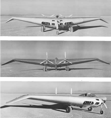
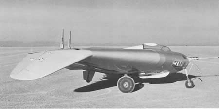
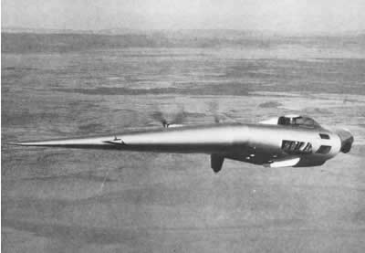
The drooped wing tips were eventually straightened on the N-1 M, as these
two views of the aircraft illustrate. With maximum tip deflection and
sweepback, and the N-1 M at rest on the tricycle landing gear, the wing
tips were only one foot off the ground. Raising the nose during takeoff
lowered the wing tips until they touched the ground while the tail wheel
was still six inches in the air. Skinned wing tips during landing or
takeoff occasionally resulted.
By November 1941,
according to Jack Northrop, 200 flights had been flown with the N-1 M,
which varied in time and altitude from a few seconds and 2 or 3 feet, to
more than an hour and 7500 feet. During this time, Moye Stephens flew the
N-1M with numerous combinations of wing tip deflection, dihedral, and
sweepback. Initially it was thought that having the wing tips deflected
downward would contribute to directional stability. It was soon found that
they had little if any effect in this regard, but did lessen lift
noticeably. Consequently, they were straightened.
With an aircraft of such
radical design, stability was one of the primary concerns. In some
configurations tested, yawing the aircraft, that is, moving the rudder
pedals to cause motion about the vertical axis of the aircraft, and then
releasing the controls, induced an oscillation called "Dutch roll." The
oscillations were intense enough that Move Stephens wondered if they would
reach a point beyond which they would be impossible to stop.
Eventually, with an alternative configuration of the
aircraft, induced "Dutch roll" damped out after three or four
oscillations.'
Of equal importance was the longitudinal stability of
the flying wing. After much adjusting, experimentation, and flight
testing, a configuration was found in which longitudinal, directional, and
lateral stability were acceptable: straight wing tips, minimum dihedral,
and the greatest degree of sweepback.
Throughout the test program, investigation of the
controllability and stability of the N-1M was frequently hampered by poor
performance and engine problems. The aircraft was overweight and
underpowered, factors that required unusual approaches to some of the
everyday problems associated with flight testing.
|
