|
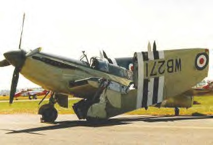
Fairey Firefly
A Fairey Firefly F.Mk I of 1772nd Squadron Royal Navy - H.M.S.
Indefatigable 1944
Before World War 11 Fairey designed a light bomber, P.4/34, from which
evolved the Fulmar naval two-seat fighter to Specification 0.8/38. A
total of 600 of these slender carrier-based aircraft served during the
war with various equipment and roles. The Firefly followed the same
formula, but was much more powerful and useful. Designed to N.5/40 - a
merger of N.8139 and N.9139 - it was a clean stressed-skin machine with
folding elliptical wings housing the four cannon and with the trailing
edge provided with patented Youngman flaps for use at low speeds and in
cruise. Unlike the installation on the Barracuda, these flaps could be
recessed into the wing.
The
pilot sat over the leading edge, with the observer behind the wing. The
main wartime version was the Mk 1, widely used from the end of 1 943 in
all theatres. Fairey and General Aircraft built 429 F.1s, 376 FR.Is
with ASH radar and then 37 NF.2 night fighters. There followed the more
powerful Mk Ill, from which derived the redesigned FR.4 with two-stage
Griffon and wing-root radiators. There were 160 of these, 40 going to
the Netherlands and the rest serving in Korea, with the 352 Mk 5s with
folding wings. There were FR, NF and AS (anti-submarine) Mk 5s. and
they were followed by the 1 33 specialised AS.6 versions with all role
equipment tailored to anti-submarine operations. The 1 51 AS.7s rounded
off production, this being a redesigned three-seater, with new tail and
wings and distinctive beard radiator. More than 400 Fireflies were
rebuilt in the 1950s as two-cockpit T.1 s or armed T.2s, or as various
remotely piloted drone versions (U.8, U.9, U.10). Some were converted
as target tugs and for other civil duties.
Variants
Designed to Admiralty Specification N.5140, calling for a two-seat
reconnaissance fighter, the Fairey Firefly represented a considerable
advance over the company's earlier Fulmar. A cantilever low-wing
monoplane of all-metal construction, it had a conventional tail unit,
retractable tailwheel landing gear and accommodation for the pilot and
navigator/radio-operator in separate enclosed cockpits. Power was
provided by a 1,730 hp (1290 kW) Rolls-Royce Griffon IIB engine, but
later production Firefly F.Mk 1 aircraft had the 1,990 hp (1484-kW)
Griffon XII. The first of four development aircraft was flown on 22
December 1941, and the first production Firefly F.Mk 1 aircraft were
delivered in March 1943. A total of 459 of this version was built, 327
by Fairey and 132 by General Aircraft under sub-contract. The addition
of ASH radar beneath the engine identified the Firefly FR.Mk 1, of
which 236 were built, and a number of Firefly F.Mk Is modified to
Firefly FR.MK 1 standard had the designation Firefly F.Mk IA. A Firefly
NF.Mk 11 night-fighter version was developed, but when it was realised
that its AI Mk 10 radar could be pod mounted beneath the engine, as
with the ASH radar of the Firefly FR.MK 1, the planned 328 aircraft
programme was cancelled. Instead, 140 Firefly FR.MK Is were modified on
the production line to Firefly NF.Mk 1 configuration, the 37 Firefly
NF.Mk IIs that had been built being converted back to Mk 1 standard.
Post-war Mk 1 conversions included the unarmed dual-control Firefly
T.Mk 1 pilot trainer, the cannon armed Firefly T.Mk 2 operational
trainer, and the Firefly T.Mk 3 used for training in ASW operations. A
few were also converted as Firefly TT.Mk 1 target tugs.
Only a prototype of the Firefly F.Mk Ill with Griffon 61 engine was
built, development being concentrated instead on the Firefly F.Mk IV.
This had a 2,250 hp (1678 kW) Griffon 74 engine and new outer wing
nacelles that could both carry fuel, or an ASH scanner (port) and fuel
(starboard). About 160 were built, and the first Firefly FR.Mk 4
delivered in July 1946; some were converted later to Firefly TT.Mk 4
standard. The Firefly Mk 5 and Firefly Mk 6 were similar externally to
the Mk 4, the first aircraft of each variant flying in December 1947
and March 1949 respectively. Some 352 Mk 5s were built in versions
designated Firefly FR.Mk 5, Firefly NF.Mk 5 and Firefly AS.Mk 5, the
last with American sonobuoys and equipment that distinguished it from
the British-equipped Firefly AS.Mk 6 of which 133 were built. A few
Firefly T.Mk 5 trainers, and Firefly TT.Mk 5 and Firefly TT.Mk 6 target
tugs were converted in Australia from Firefly AS.Mk 5s.
The
first production Griffon 59-powered Firefly AS.Mk 7 was flown in
October 1951, this reintroducing the beard radiator that had caused
problems with the sole Mk Ill. Intended as an ASW aircraft
accommodating two radar operators, few Fireflys AS.Mk 7s were built as
such, the majority being completed as Firefly T.Mk 7 ASW trainers
within a Mk 7 production of 151. Later conversions to pilotless target
aircraft were carried out by Fairey, these including 34 Firefly U.Mk 8
aircraft converted from Firefly T. Mk 7s, and 40 similar Firefly U.Mk 9
conversions from Mk 4 and Mk 5 aircraft. They were used for missile
development, and by the Royal Navy as targets for its Firestreak-armed
fighters and Seaslug-carrying ships.
Fireflies entered service first with No. 1770 Squadron at Yeovilton,
Somerset, on 1 October 1943. Later embarked on HMS Indefatigable, they
were active in operations against the German battleship Tirpitz in
Norway during July 1944. They also saw action against Japanese oil
refineries in Sumatra, in attacks on the Carolines and against shipping
and ground targets in the Japanese home islands. In 1950, after war
broke out in Korea, Firefly Mk 5s were operated from Australian and
British light fleet carriers, and in 1954 the type was in action in the
ground-attack role in Malaya. Just over two years later the Firefly was
retired after 13 years of valuable service.
Specifications (Fairey Firefly AS.Mk 5)
Type: Two Seat Naval Reconnaissance Fighter / Anti Submarine Strike
Aircraft
Design: Fairey Aviation Design Team
Manufacturer: The Fairey Aviation Company
Powerplant: (AS.Mk 5) One 2,250 hp (1678 kW) Rolls-Royce Griffon 74
12-cylinder Vee piston engine. (Mk I up to No 470) One 1,730 hp (1290
kW) Rolls-Royce Griffon IIB 12-cylinder Vee liquid-cooled; (from No
471) 1,990 hp (1485 kW) Griffon XII. (Mks 4-7) One 2,250 hp (1678 kW)
Griffon 74 12-cylinder Vee piston engine.
Performance: (AS.Mk 5) Maximum speed 386 mph (618 km/h) at 14,000
ft (4265 m); cruising speed 220 mph (354 km/h); service ceiling 28,000
ft (8534 m). (Mk I) Maximum speed 316 mph (509km/h); initial climb rate
1,700 ft (518m) per minute; service ceiling 28,000 ft (8534 m). (Mk 4)
Maximum speed 386 mph (618 km/h); initial climb rate 2,050 ft (625 m)
per minute; service ceiling 31,000 ft (9450 m).
Range: (AS.Mk 5) 1300 miles (2092 km) on internal fuel. (Mk I) 580
miles (933 km) on internal fuel. (Mk 4) 760 miles (1223 km) on internal
fuel.
Weight: (AS.Mk 5) Empty 9,674 lbs (4388 kg) with a maximum take-off
weight of 16,096 lbs (7301 kg). (Mk I) Empty 9,750 lbs (4422 kg) with a
maximum take-off weight of 14,020 lbs (6359 kg). (Mk 7) Empty 11,016
lbs (4997 kg) with a maximum take-off weight of 13,970 lbs (6337 kg).
Dimensions: (Mk 4 - 6) Span 41 ft 2 in (12.55 m); length 37 ft 11
in (8.51 m); height 14 ft 4 in (4.37 m); wing area 330.0 sq ft (30.66
sq m). (Mk I - III) Span 44 ft 6 in (13.55m); length 37 ft 7 in (11.4
m); height 13 ft 7 in (4.15 m).
Armament: (Mk I) Four fixed 20 mm Hispano cannon in wings and
underwing racks for up to two 1,000 lbs (454 kg) of bombs or sixteen 60
lbs (27 kg) rocket projectiles. (Mk 4 and 5) usually similar to 1 in
most sub-types. (Mk 6) no guns, but underwing load increased to 3,000
lbs (1362 kg) and varied. (Mk 7) no guns, but underwing load remained
at 3,000 lbs (1362 kg) and equipment changed.
Variants: Firefly F.Mk 1, Firefly FR.Mk 1, Firefly F.Mk IA, Firefly
NF.Mk 11, Firefly NF.Mk I, Firefly T.Mk 1, Firefly T.Mk 2, Firefly T.Mk
3, Firefly F.Mk III, Firefly F.Mk IV, Firefly FR.Mk 4, Firefly TT.Mk 4,
Firefly Mk 5, Firefly Mk 6, Firefly FR.Mk 5, Firefly NF.Mk 5, Firefly
AS.Mk 5, Firefly AS.Mk 6, Firefly TT.Mk 5, Firefly TT.Mk 6, Firefly,
AS.Mk 7, Firefly T.Mk 7 ASW, Firefly U.Mk 8, Firefly U.Mk 9.
Avionics: AI Mk X radar, ASH Scanner, sonobuoys.
History: First flight 22 December 1941; first production F.1 26
August 1942; production FR.4. 25 May 1945; final delivery of new
aircraft May 1955.
Operators: United Kingdom (RN), Canada (RCN), Australia.
Number Built: ~1533
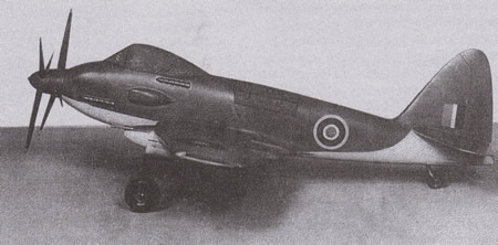
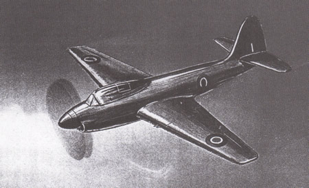
Fairey’s
Strike Fighter Concept: 1944
Raul Colon
May 5th. 2009
Email:rcolonfrias@yahoo.com
In late August 1944, the Fairey
Corporation was asked to asses the feasibility of adapting
its original tandem, twin engine research studies to a new
naval strike platform. The British Royal Navy issued a
verbal requirement statement in October asking for a twin
tandem aircraft fitted with a Tandem Merlin power plant,
codenamed Project A, and alternative Twin Griffon platform,
known as Project B. Either design was intended to be a
single seat fighter, although there was the possibility of
adding a rear compartment for a navigator.
The initial single seat platform design was very similar in
form to the Fairey’s O-21-44 Torpedo Bomber. The main
difference was a contra-rotating propeller system. Two heavy
calibre cannons were fitted underneath each wing nacelles,
the structure that also housed the main undercarriage. One
torpedo or a 2,000lb bomb load could be carried on the
plane’s centreline. The wings could also carry up to one
thousand pound bomb load under each inner wing.
Project A
was designed to carry a 300 gal fuel load internally and
additional 520 gal on drop fuel tanks. The plane's projected
top speed at a 20,000’ operational ceiling was estimated at
460 mph. Top service ceiling was 36,000’, but with a torpedo
load it fell to 29,600’. With drop fuel tanks, the aircraft
was able to operate at a distance of 820 miles. Project B or
Griffon carried a similar profile. Top speed was determined
at 397 mph with a top ceiling of 38,000’. Bomb load capacity
was the same as the A program. The only other variant visa-vise
the Merlin centred project was that the Griffon projected an
860-870 miles operational range, between forty to fifty
miles longer than the Merlin. Nevertheless, it was the
Merlin in which the company pitted their hopes for a new,
huge production contract. But the fact of the matter was
that Project A did not measure up to the concurrent Westland
N-11-44 design.
During the first weeks of March 1945, Fairey redesigned the
“A”’s overall specifications. The plane would still employ
the Merlin RM-17sm power plant, but the new version was
streamlined and compacted. The new concept was a welcome
sight to many inside the Ministry of Aircraft Production
(MAP) who were uneasy about the path the whole program was
taking. The new version of Project A had a better climb rate
than the Westland and a more robust undercarriage, a most
important consideration for naval operations. Still, the
Westland was considerably faster than the “A”. One factor
would change the dynamics of the “A”. By the middle of 1945,
engineers at Fairey and other British aircraft manufacturing
companies were adapting to a new kind of engine, the gas
turbine. The Merlin had achieved its peak of aerodynamic
design and now it was time to replace it with a more
flexible unit.
Fairey was quick to adapt to the new realities and promptly
began to design the “A” with a turbine propeller alignment.
With MAP consent, Fairley field officials commenced informal
discussion with Rolls-Royce engineers regarding the
availability of the Clyde engine as well as other jet
propeller gas turbine power plants under development.
Rolls-Royce gave the company advance data research
information for three top secret turboprop engines, RB-52
(an improved Clyde), RB-52-30 and RB-52-50. After
redesigning the “A” program with each of the three
prototypes, Fairey determined that the twin Merlin
configuration gave a better overall performance, thus
prompting the company to conclude that the expected high
cruising fuel consumption of the single turbine power plant
running in a throttle environment was the main culprit of
the “A” poor showing in contrast to the Westland. The
project managing team at Fairey decided to implement a small
twin turbine configuration which would drive a
contra-rotating propeller in a similar manner to the tandem
piston system. It was envisioned that this alignment would
give the “A” a better overall profile that a single turbine
of equal aggregate power.
Soon after the engine configuration decision was achieved,
the company commenced work on two new strike fighters. The
first would utilize a single RB-52-50 turboprop with a
contra-rotating propeller. The other example was fitted with
two B-52-30 arranged in tandem with a separated
contra-propeller gearbox with each propeller driven by its
own turbine system.
A
specification and profile paper was submitted to the MAP in
June 30th 1945 featuring three planes. Each had a 52 feet
wing span, four 20mm heavy calibre cannons and a torpedo
arrangement. The piston configuration (RB-52-30) offered a
total weight of 23,900lb, with a maximum speed of 410 mph at
a 10,000’ ceiling. The RB-52-50 weighted at 24,400lb with a
top speed of 395 mph and the same armament arrangement. The
Clyde’s profile was similar to the other two, only its
airspeed (413 mph) and total weight (23,300lb) was
different.
Following Fairey’s paper the MAP concluded that a single
Clyde system was inferior to the twin Merlin arrangement on
almost all areas. But the higher achieved power gave the
Project A an overall systematic quality that exceeded,
albeit not by much, the one profiled on the Westland (now
known as the N-11-44 project). The Admiralty gave the
company the official ‘go ahead’ to start pre-production
development on the strike fighter in September 1945. The
Royal Navy made it official on June 20th 1946 when it issued
Specification N-16-46.
With the end of the war in May 1945, the MAP began to review
all incomplete aircraft programs. All Rolls-Royce engines
designs were also reviewed. The company was asked to issue
its views regarding the standing of their twin-tandem piston
engine in regards to the new turboprops. In October,
Rolls-Royce stated that it was in favour of utilizing the
Fairey’s twin turboprop arrangement for navalized version of
the strike fighter project. At the same meeting, Rolls
executives told the Ministry members and Fairey senior staff
that eventually the company would shift its engine
developmental resources towards an axial flow jet engine.
Fairey got the message and abandoned its tandem system
altogether. Now, the company’s main military project would
be fitted with a side-by-side engine system housed behind
the main gearbox. Rolls accepted the idea and a new engine
system was born, call sign AP-25.
The changes to the engine system caused the alteration of
the original overall plane layout. The aircraft that emerged
after the redesign program was a much cleaner unit. It had a
completely clean trailing edge without hinge brackets, which
was a mainstay of Fairey’s recent designs. The wing
structure was laminated to allow an even air flow. The main
armament, the torpedo, was still housed on the airframe’s
centreline but now bombs, depth charges, rockets or any
supplemental weapon system would be carried under the wing
outboard of the main undercarriage between and below the
heavy cannon. The two side-by-side engine configuration
drove its own propeller through an independent mechanism
train carried by a central gearbox. The two jet pipes
exhausted through the bottom of the fuselage just behind the
wing area. Internal fuel capacity, with a torpedo profile,
was now 545gal. Top operational ceiling was estimated at
49,000’. There were plans to convert the Program A and B
into a single entity with a two-seated arrangement.
A complete aircraft layout was submitted to NE Rowe, the
MAP’s new Deputy of Development and Production on November
13th. Rowe accepted Fairey’s statement that Rolls would have
the new AP-25 engine ready for operational testing by
December 1946. On the morning of November 21st, Rowe advised
Fairey of a MAP amendment to the original specification
profile. The new order called for a true dedicated dive
bombing platform, instead of the strike fighter boxed role
first envisioned. On January 2nd 1946, the Admiralty issued
a new set of pre-production order for the aircraft with a
target date of January 1948. Immediately Fairey ran into
pre-developmental problems. First, the now dive bomber
proved to be too heavy for naval operations forcing the
engineering team to shed almost 1,000lb of weight, most of
them from the reinforced steel main fuselage. More
importantly to Fairey than the weight issue was the
development delays confronting Rolls Royce.
On October 17th, Royce executives advised their Fairey’s
counterparts on the delays facing the engine, now known as
Coupled Tweed, but still expected the power plant to be
ready by the following January. By early 1947, the Admiralty
was increasingly sceptic of the whole dive bomber/strike
fighter concept. Their top leaders could not cover the high
amount of monetary resources the Fairey platform was
‘eating’ yearly. For them, the time of the dive bomber has
log passed and on March 12th, it made it official with the
cancellation of the entire program.
For Royce, the termination of the project marked a shift in
the company’s priorities and investments. As for Fairey, the
company enjoyed a few success stories afterward. In the
months following the cancellation, the engineers that worked
on the strike program, as well as all the data collected on
it, was used on the Gannet Program.
Fairey Aircraft Since 1915, HA Taylor,
Putnam 1974
RAF Bomber Command and its Aircraft 1936-1940, James
Goulding and Philip Moyes, Ian Allan 1975
Planemakers II, David Monday, Janes 1982
|
