|
Airfoils
The
historical evolution of airfoil sections, 1908-1944.
The last two shapes are low-drag sections designed to have laminar flow
over 60 to 70 percent of chord on both the upper and lower surface.
The Wright brothers had done some of the
earliest research on the most effective curvature, or camber, of a wing,
known as an airfoil. But during the early years of powered flight,
airfoils for aircraft were essentially hand-built for each airplane.
Before World War I, there had been little research to develop a
standardized airfoil section for use on more than one aircraft. The
British government had performed some work at the National Physical
Laboratory (NPL) that led to a series of Royal Aircraft Factory (RAF—not
to be confused with the Royal Air Force) airfoils. Airfoils such as the
RAF 6 were used on World War I airplanes. Most American airplanes used
either RAF sections or a shape designed by Frenchman Alexandre Gustave
Eiffel (best known for designing the Eiffel Tower).
The mean
camber line shown in this illustration is the line that is equidistant
at all points between the upper and lower surfaces of the airfoil.
When the National Advisory Committee on
Aeronautics (NACA) was established in 1915, its members immediately
recognized the need for better airfoils. The first NACA Annual Report
stated the need for "the evolution of more efficient wing sections of
practical form, embodying suitable dimensions for an economical structure,
with moderate travel of the centre of pressure and still affording a large
angle of attack combined with efficient action."
NACA explained its first work with
airfoils in 1917 NACA Technical Report No. 18, "Aerofoils and Aerofoil
Structural Combinations." The authors noted that mathematical theory had
not yet been applied to airfoil design and most of their work was trial
and error. They had tested a number of brass airfoil models with a span of
18 inches and a chord (or maximum width) of 3 inches in a wind tunnel.
With this report, they introduced the U.S.A. series of airfoils and
reported wind tunnel data for the U.S.A. 1 through U.S.A. 6 sections. The
authors stated that slight variations in airfoil design resulted in large
differences in aerodynamic performance, a fact that required extensive and
careful research in order to obtain the best possible performance from an
airfoil.
In 1933, NACA issued its monumental
Technical Report No. 460, "The Characteristics of 78 Related Airfoil
Sections from Tests in the Variable-Density Wind Tunnel." The authors of
this report described the NACA four-digit airfoil series. The four digits
defined the overall shape of the airfoil. For instance, NACA airfoil 2412
had a maximum camber of 2 percent of the length of the chord, represented
by the first digit; the maximum camber occurred at a distance of 0.4 chord
(or 4/10 or 40 percent) from the leading edge, indicated by the second
digit; and the maximum thickness of the airfoil was 12 percent (0.12) of
the overall width (or chord length) of the wing, represented by the last
two digits. So if airfoil 2412 has a chord length of 10 feet, its maximum
camber would be (0.02)10 = 0.2 feet; the maximum camber would be located
40 percent (0.4) away from the leading edge – (0.4)10 = 4 feet; and the
maximum thickness of the airfoil would be 0.12(10) = 1.2 feet.
Not all 78 airfoil sections would
necessarily be used by airplane designers, but the testing data gave
aircraft manufacturers a wide selection. After this report was published,
the NACA airfoils became widely used, and the NACA 2412 continued in use
on some light airplanes more than half a century later.
NACA Technical Report 460 represented a
major contribution to the development of the airfoil. The information in
the report eventually found its way into the designs of many U.S. aircraft
of the time, including a number of important aircraft during World War II.
The DC-3 transport, the B-17 Flying Fortress bomber, and the twin-tailed
P-38 Lightning interceptor airplane all relied upon the airfoil
information in Report 460.
In the late 1930s, the NACA performed
more research on airfoils with the goal of increasing maximum
lift. This resulted in the NACA five-digit airfoil series and airfoils
such as the 23012, which is used on the Beechcraft Bonanza aircraft. The
first digit and the last two digits in this series designate camber and
thickness as in the four-digit series. However, the second digit indicates
twentieths of a chord rather than tenths as in the four-digit series (3/20
in this example). And the middle digit is used to indicate either a
straight mean camber line (0) or a curved mean camber line (1). (The mean
camber line is the line that is equidistant at all points between the
upper and lower surfaces of the airfoil. It is also referred to as the "meanline.")
One of the problems with the NACA
airfoil research performed up until the late 1930s was that
aerodynamicists could not test an entire wing section. They did not have a
wind tunnel big enough to mount an entire wing and so they tested only a
part of the wing and then extrapolated the data to a full wing. But the
problem with this approach was that the researchers could not determine
the effects of the airflow at the tip of the wing, which was often quite
important to understanding its overall performance.
This changed in 1939 when the NACA
constructed a new low-turbulence two-dimensional wind tunnel at Langley
Research Center in Virginia. This wind tunnel was exclusively dedicated to
airfoil testing. Once it was constructed, NACA aerodynamicists conducted a
huge number of tests in the wind tunnel on a wide range of airfoil
designs.
By the end of the 1930s, NACA
aerodynamicists had turned their attention to laminar-flow airfoils
(laminar flow relates to the smooth flow of air over a structure). The
laminar-flow airfoils (NACA's six series) were shaped with their maximum
thickness far back from the leading edge. The first aircraft to use the
laminar-flow airfoils for their low-drag qualities was North American's
P-51 Mustang, and they are still used quite extensively today on many
high-speed aircraft. Although, in most cases, when used in actual flight
outside of the wind tunnel, these airfoils behaved much like traditional
airfoils, they proved to have excellent high-speed characteristics—an
unexpected but welcome result.
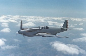
The
North American XP-51 Mustang was the first aircraft to incorporate
a NACA laminar-flow airfoil. It was used extensively during World War II.
NACA airfoil development was virtually
halted in 1950 as the aerodynamicists switched their attention to
supersonic and hypersonic aerodynamics. But in 1965, Richard T. Whitcomb
developed the NASA supercritical airfoil. This was a revolutionary
development, for it allowed the design of wings with high critical Mach
numbers, which can operate at high speeds.
After Whitcomb's breakthrough, the
National Aeronautics and Space Administration (NASA), which was created in
1958 and absorbed the NACA, revived U.S. airfoil research. It developed a
low-speed airfoil series for use by general aviation on light airplanes.
These low-speed airfoils, designated LS(1), LS(2), and so on, have better
lifting characteristics than their predecessors and allow smaller wing
areas—and hence less drag—for small private aircraft. But it is not
uncommon to find aircraft in operation today that still use the NACA
four-digit and five-digit airfoil sections developed in the 1930s and
1940s.
|
